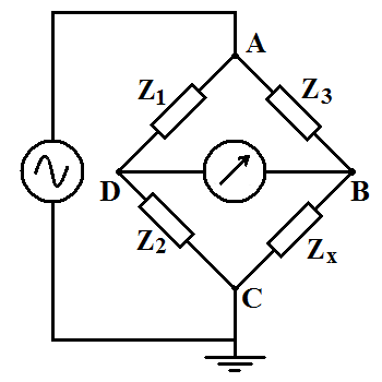
The alternating current electrical circuits known as “AC Bridges” are employed to determine or measure unmeasured capacitance, inductance, and resistance. These measuring devices only function with an AC source and are comparable to DC Bridges (such as Wheatstone Bridge, Kelvin’s Bridge, etc.). The process is based on the comparison measurement approach, which compares the unknown value with the known value when the bridge circuit is balanced.
What is an AC bridge?
Electrical characteristics like resistance, capacitance, and inductance are tested using circuits known as AC bridges. In addition, we can also try storage factor, loss factor, dissipation factor, and other parameters using an ac bridge. AC bridges operated with AC signals. An AC bridge uses a phase shift and provides the oscillator with a feedback loop.
Construction
- The bridges are pretty easy to build. Four arms, one AC power source, and a balanced detector make up The Bridge. It operates on the tenet that the circuit will be in balance according to the null detector’s determination of the impedances’ balance ratio.
- Two opposing junctions are attached to a balanced detector, while the other two opposite junctions couple to an ac voltage source at the appropriate frequency. As a flat detector, headphones or vibration galvanometers are used, depending on the frequency of the original. Balance detectors use in conjunction with vibrational galvanometers in ac bridges. Vibrational galvanometers only respond to the fundamental frequency they tune as tuned sensors.
- Frequency and supply waveform are vital factors when it comes to ac bridges. But it would be exceedingly challenging to achieve the balancing situation if the supply waveform has any harmonics.
- As a result, the frequency fluctuation will make it difficult to achieve equilibrium (since the balance equation in ac bridges is a function of frequency). Since the vibrational galvanometer will not detect other frequencies and harmonics, it will only respond to the resonant frequency.
AC Bridges errors
- Residual Errors: Although bridge circuits are supposed to be non-inductive and non-capacitive, residues are tiny quantities of intrinsic inductance or capacitance that are always present despite their inductance and capacitance is zero. It is crucial to evaluate these components to stop the emergence of these issues.
- Frequency errors: Frequency mistakes, also known as sinusoidal waveform fluctuations brought on by the existence of harmonics in the supply, are a significant contributor to the generation of noticeable crossings in the supply system.
- Effects of Stray Conductance: Errors may occur due to leakage currents from one arm to another in a bridge circuit if there is improper insulation between the various components. Typically, a high-impedance bridge experiences this. Device parts and other features are positioned on an insulating platform to get around this issue.
- Eddy Current Errors: The Bridge’s traditional values vary due to the induced eddy currents in the standard resistors and inductors. It is best to keep materials with high conductivity masses away from the Bridge.
- Electrostatic coupling-related errors: If the neighboring branches of a bridge network are at different potentials, the inter-capacitance effect will occur. In other words, interactions between the electric fields of the units produce faults. By enclosing the components with earthed metallic shields, efficient shielding might lessen this error.
- Electromagnetic coupling errors: The source will immediately create an emf in the sensor if there is electromagnetic coupling between it and the detector. The detector shows zero when the Bridge produces a voltage opposite in phase and equal in amplitude to the induced emf.
Read More: Display Your Daily Apparel with Custom Belt Boxes Wholesale.
Impedance Bridge
Impedance bridges function similarly, except that the balancing equation uses complex numbers since the magnitude and phase of the two divisions’ components must be identical for the null detector to display “zero.” Of course, the null detector has to be a piece of equipment that can pick up extremely low AC voltages.
Null Detector for AC
Utilizing an impedance-matching transformer to link audio headphones to the signal source can help you get the most out of their abilities as null detectors. A step-down transformer assists in “matching” low-current signals to the impedance of the headphone speakers since they often have low-impedance units (8 ), which need significant current to drive.
Wien bridge
Every capacitor has some internal resistance, whether actual or equivalent (in the form of heating losses in the dielectric), which tends to ruin their otherwise perfectly reactive natures. Compared to the previous Bridges we’ve looked at, this one will take a little longer to balance because two standard components need to be changed (a resistor and a capacitor).
The magnitude and phase angle is altered by the Rs and C’s combined actions until the Bridge finds an equilibrium state. The calibrated knobs on those instruments may then be used to calculate the values of Rs and Cs. The balancing equation (Z1/Z2 = Z3/Z4) may be used to estimate the unknown capacitance and resistance hypothetically. Thus, it is theoretically possible to calculate the parallel impedance of the two.
The standard capacitor has relatively little internal resistance when the Wien bridge operates. At least now that the opposition is recognized, the calculation for balancing may consider. When the internal resistance of “lossy” capacitor types like electrolytes is relatively large, Wien bridges help estimate their values.
